|
|
 Software Solutions- Inter Changeability- Software Solutions- Inter Changeability-
|
 1DCS (One dimensional Tolerance Analysis Tool)
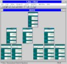
1DCS is a World Class Linear Tolerance Analysis Tool that allows users to quickly develop and analyze various design objectives through the comparison of different tolerancing schemes. 1DCS offers users the ability to allocate tolerances to determine the component capability required to meet overall assembly objectives (Roll-down or Top-Down), as well as determine the overall assembly variation based on actual tolerance capability (Roll-Up or Bottom-Up). Studies testing Alternative Tolerancing Schemes and Assembly Sequences can help to identify the most "Robust" Design & Manufacturing Alternatives.
1DCS has a simple, graphical user interface that is very easy to use. Requires no or minimal training to use, but the output greatly helps in key decision making process.
Graphical User Interface:
1DCS is a Graphics-Based Package.It employs a Graphical User Interface that allows for rapid development of tolerance studies, and requires a minimal amount of effort to learn. Anyone having basic computer skills can perform tolerance analysis.
Predict & Display Assembly Variation:
Because 1DCS is Graphical in nature, The assembly and assembly sequence are displayed in a descriptive tree and histograms are used to graphically display the assembly tolerance, with red bars indicating the out of spec condition.
Complete Statistical Data:
1DCS uses a Random Number Generator to assign a value for each tolerance during each and every Simulated Build. The simulation method can be selected from Monte Carlo, RSS, or Worst-Case, and users can import actual part data for even more accurate results. The Distribution Type for each Tolerance can be select from a list of distribution-types or a best-fit curve can be calculated to match your data. The output of each simulation comes in the form of Complete Statistical Results that include, Standard Deviation, % Out of Spec, Tolerance Ranges, and a Histogram that graphically displays the distribution for each measurement in the model
Complete Assembly Diagrams:
Determining the best assembly sequence is paramount to simultaneous engineering. To make it possible, 1DCS uses a simple assembly tree to display the relationships between parts and sub-assemblies. Each part, sub-assembly, and fixture is identified in the correct assembly sequence and each element in the assembly tree is assigned it's associated tolerance. This tree serves as a quick and user-friendly interface through which the user can perform required studies.
Automatic Report Formatting & Database Connectivity:
1DCS is a Graphics-Based Package.It employs a Graphical User Interface that allows for rapid development of tolerance studies, and requires a minimal amount of effort to learn. Anyone having basic computer skills can perform tolerance analysis.
 DCS-DFC Datum Flow Chain
Visually Analyze Dimensional Requirements:-
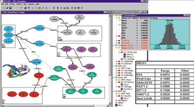
A Datum Flow Chain (DFC) is a graphical diagram that defines the relationships between assembled parts, assembly fixtures, tooling and equipment all within one model and provides analysis along any selected 1-D path of a Cartesian coordinate system. "Master" DCS-DFC models of complete assemblies are created and then accessed by many users, allowing for "what if" studies to be performed on particular areas of interest. With an intuitive graphical user interface employing "point & click" operations, DCS-DFC is a premier tool for facilitating assembly-first product design where part tolerances can be optimized for cost reduction.
DCS-DFC's easy-to-read dialog boxes are used to identify part datums, locating features, and control tolerances for part features within the assembly. A DCS-DFC uses this input information to predict the variation for each defined measurement specification. Unlike typical 1-D analysis solutions, DCS-DFC allows users to link feature tolerances to more than one specification or measurement and analyze multiple assembly measurements of a complete system within a single report. Statistical calculations such as standard deviation, percent out of specification, Pp and Ppk, confidence intervals and many more are calculated and displayed by DCS-DFC in a variety of graphic output formats for generating reports.
Business Values:-
Utilize graphic schematic modeling of complete 3-D assemblies with an organized presentation tool for describing assembled part relationships. Analyze along any selected 1-D path using several methods: Worst Case (straight stack), RSS (Root-Sum-Square) and Monte Carlo Simulation. Analysis results are represented graphically in the model and analysis outputs can be reported in a variety of formats.
DFC-Tree - View Image
Target Users:-
DCS-DFC Datum Flow Chain An innovative tool for those in the entire engineering community to achieve build quality objectives through strategic planning and analysis of assembled part relationships
Key Product Features:-
- Graphically Define an entire system simultaneously in a single model.
- Custom User Layouts for parts, features, and measurements can be hidden or displayed on separate layers for ease in viewing and reporting.
- Automatic hole/pin float calculations from hole/pin relationship and size tolerance.
- Multiple Analysis Options: Worst-Case, RSS & Monte-Carlo Simulation.
- Check for over-constrained/under-constrained datum reference frames.

3DCS Analyst
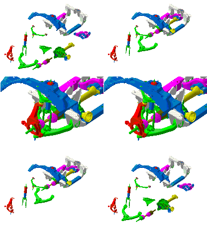
3DCS is a World Class 3D Tolerance Simulation Tool that allows you to model the effect of variation on an assembly, Determine the "Robustness" of your design, and test Alternative Tolerancing Schemes. 3DCS is a True 3D Tolerance Modeling system that visually depicts variation in your design, and statistically simulate production of your "Virtual Assemblies."
Modeling Variation Graphically:
3DCS employs a 3-Dimensional Display that is unique in its class. The User Interface is similar to many high-end CAD systems and allows you to Pan, Zoom, and Manipulate the True 3-D Parts and Assemblies. Parts can be imported into the software from almost any CAD system as IGES data, or simple parts can be created directly in the Software.
Easy to Use Menus:
3DCS is designed to run on the Windows operating systems, so it makes full use of the Simple Windows User Interface. Clear Menus and Toolbars allow for the quick generation of models. An Engineer or designer familiar with CAD systems can be modeling parts and assemblies in just 3-4 days.
Visualize Variation in Real Time:
Because 3DCS is Graphical in nature, you will actually be able to see the variation as it is simulated. Features vary based on GD&T callouts, parts move in their assemblies, and measurements change. If a picture is worth a thousand words, imagine the value of viewing an animated assembly sequence and assembly variation!
Complete Statistical Data:
3DCS uses a Monte Carlo Random Number Generator to assign a value for each tolerance during each and every Simulated Build. You can select a Distribution Type for each Tolerance from a list of distributions-type that include, Normal, Weibull, Uniform, and User-Defined. The output of each simulation comes in the form of Complete Statistical Results that include, Standard Deviation, % Out of Spec, Tolerance Ranges, Cp, Cpk, and a Histogram that graphically displays the distribution for each measurement in the model.
Complete Assembly Diagrams:
Following an exact assembly sequence is critical when modeling variation in an assembly. To make that possible, 3DCS uses an assembly tree to display the relationships between parts and sub-assemblies. Each part, sub-assembly, and fixture is identified in the correct assembly sequence and each element in the assembly tree shows it's associated moves, measures and tolerances for quick assessment of the model.
Key Contributors to Variation:
Determining the Root-Cause of Variation in an assembly is one of the most important aspect of Variation Simulation. That's why 3DCS identifies Key Contributor for each and every measurement in your model. 3DCS provides designers and engineers an analysis of the extent and source of variation in a model. This allows for Pareto Analysis, as well as a study of Sensitivity in the model. Predicting dimensional variations due to part tolerances as well as assembly process sequences are significant early in the design process before investing into tooling, prototyping and production fixtures and inspection gages.

Graphic Tolerance Simulation Software Solutions for CATIA V5


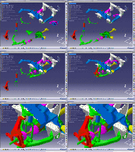
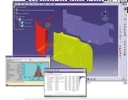
Visually Observe Dimensional Variation :
Predicting dimensional variations due to part tolerances as well as assembly process sequences are significant early in the design process before investing into tooling, prototyping and production fixtures and inspection gages.
3DCS provides the power to define, test and modify product and process requirements in a digital environment and the ability to share reliable variation analysis results with the entire product development team. Utilizing 3DCS will enhance existing manufactured products and enable the cost-effective development of exciting new fast-to-market products.
Modeling Variation Graphically:
3DCS Designer, CAA V5 Based Graphic Tolerance Simulation Software embedded within CATIA V5
A completely feature-based versatile solution focused specifically on the needs of designers and engineers, 3DCS Designer is a powerful dimensional analysis tool that predicts the amount of part and process variation and highlights their causes. 3DCS Designer quickly evaluates part GD&T early in the product development stage so that desired fit and function (gaps, flush, overall dimensions) specifications are achieved in production.
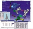
3DCS Analyst, CAA V5 Based Graphic Tolerance Simulation Software embedded within CATIA V5.
With all the same feature-based routines of 3DCS Designer, plus a comprehensive set of point-based routines that provide greater flexibility and a higher degree of accuracy, 3DCS Analyst is the ideal tool for complex tolerance simulation modeling of part and process variation in multi-stage assemblies. 3DCS Analyst allows manufacturers to prevent build problems by quickly evaluating assembly GD&T, tooling and sequencing ahead of time.
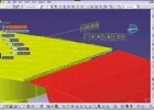
Business Values:
Optimize Product Designs and Processes
3DCS, CAA V5 Based allows CATIA users to evaluate design and assembly concepts up front, where problem areas can be identified early in the product development cycle. Optimizing for dimensional integrity improves the robustness of design and processes by maximizing part tolerances while controlling the dimensional assembly requirements of the final assembly.
Reduce Cycle Time & Rework Costs
Shorten development time, accelerate time to market and reduce costs by utilizing the capability of 3DCS, CAA V5 Based for digital prototyping. By maximizing part tolerances while still controlling dimensional assembly requirements, manufacturing costs can be reduced with less rework to tools and gages, minimized scrap and reduced number of warranty defects. 3DCS, CAA V5 Based reduces your bottom line and significantly improves product quality by validating that parts fit and function together before production starts.
Target Users
3DCS, Designer, CAA V5 Based
A core solution to meet the day-to-day demands of designers and engineers
3DCS, Analyst, CAA V5 Based
A comprehensive tool for specialists who need to perform complex iterative analysis
Key Product Features

- Identify Contributors - Localize tolerances and assembly processes responsible for variation
- Incorporate embedded CATIA V5 FTA or CATIA V4 FD&T and visually display part variation
- Identify Contributors - Localize tolerances and assembly processes responsible for variation
- Work Seamlessly with existing CATIA V4 data
- Animate Build Sequences - Create exploded views and display parts moving sequentially to their final assembled positions
- Animate Variation On-Screen - Users can visualize clearances & interferences, sweep parts and assemblies within their statistical extremes
- Quickly Build Analysis Models with an easy-to-use and easy-to-learn graphical user interface, all within a single CATIA V5 window
- Create Models Without Geometry - Perform tolerance analysis with 3DCS, Analyst, CAA V5 Based before CAD geometry exists
- Specify Distribution Types - Select from a comprehensive set of statistical distributions with 3DCS, Analyst, CAA V5 Based to represent differing manufacturing processes
- Supports both Windows and UNIX Operating Systems
- Three Types of Analysis Outputs - Monte Carlo Simulation, High-Low-Mean (Sensitivity Analysis) and GeoFactor Analysis
- Perform What-If Analysis - Learn the impact on the final assemblies before costly design changes need to be made
- Evaluate Geometric Factors in critical dimensions of parts and assemblies and enhance the robustness of their designs
- Reuse Models - Capture commonly used processes and build your own library of easily accessible models
- Update Models Automatically - Direct links to design geometry result in quick and efficient tolerance model updates
- Enhance Dimensional Integrity with greater product quality and improve Product Lifecycle Management
- Use Manufacturing Data - Import real world data into 3DCS, Analyst, CAA V5 Based for root cause analysis to improve existing build processes
- Communicate Results quickly and simultaneously to the entire product development team
 GDM-3D-
Graphic Data
Management-3D
Making Dimensional Data the Lifeline
of Your Manufacturing Process
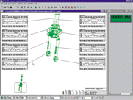
GDM-3D Specialist - Three Dimensional Graphic Data Management Software for the CMM User. A low cost solution containing versatile capabilities focused specifically on the needs of a single CMM user, GDM-3D Specialist is a powerful dimensional quality management tool for reporting the amount of individual part and manufacturing process variation and highlighting their cause.
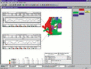
GDM-3D Analyst - Three Dimensional Graphic Data Management Software for the production environment. In addition to all of the capabilities of GDM-3D Specialist, GDM-3D Analyst facilitates the needs of multiple CMM users within the production environment. GDM-3D Analyst is the complete dimensional quality data management tool for reporting manufacturing process variation in a rich solids-based graphical environment.
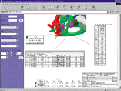
GDM-3D Corporate - Three Dimensional Graphic Data Management Software for the entire corporation. A fully customizable solution to meet the specific needs of large scale manufacturing operations, GDM-3D Corporate is a "turn-key" database-enabled solution for dimensional data management, starting from equipment operator interface to deployment of quality engineering reports on the web.
Business Values
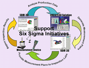
GDM-3D provides a variety of methods to track improvements in overall quality while graphically identifying and statistically analyzing areas for improvement. GDM-3D standardizes the quality reporting process to improve communication. With multiple tools incorporated into a single package, there is no need to purchase separate solutions for quality reporting. Import and read data from ANY measurement device. Reduce the time and costs inherent with evaluating tedious "raw" data and begin reporting and analyzing information as it becomes available directly from your measurement databases or inspection devices.
Target Users
GDM-3D Specialist A competitively priced tool for single CMM users to report collected data including Gage R&R and PPAP
GDM-3D Analyst A complete data management tool to meet the needs of multiple CMM users in any production environment
GDM-3D Corporate A comprehensive and customizable tool for analyzing and reporting dimensional quality data across the entire design and manufacturing organization
Key Product Features
- Complete set of SPC calculations
- Configurable color indicators to quickly "flag" potential problem areas
- Customizable Chart Types for Gage R&R, Measurement Plans, Prototype, Production or Historical Checking
- Open Connectivity with ANY database or inspection equipment
- Direct Link to Dimensional Control Systems' 3DCS tolerance simulation software
- Web-Based deployment of quality engineering reports
- Combine 3-D CAD solid geometry with dimensional data into a single report
- Compare individual part and/or assembly data and multiple build processes
- "Drag and Drop" positioning of charts and graphics in an easy-to-use interface
- Supported on the Windows Operating System
- CAD Functionality: pan, rotate, zoom, create
|
|


 Software Solutions- Inter Changeability-


 PC-DMIS