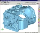
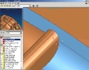
 CADfix Product Overview

CADfix provides a solution for the problems of data exchange and re-use between different incompatible CAD/CAM/CAE softwares and applications.. It allows the user to import CAD geometry and then to repair and manipulate it to a form most suitable for the downstream application - with the main objective of eliminating expensive CAD model repair and tedious rework.
The 5 Stage CADfix Wizard offers an automatic processing capability for fixing the CAD geometry to a valid well connected face or solid model. The Wizard is supported by an extensive set of interactive geometry manipulation tools for use as required.
CADfix also offers model defeaturing utilities which are very popular with CAE analysis users who defeature the model with operations such as the joining or collapsing of short edges and small faces, and automatic hole and fillet removal.
The CADfix geometry preparation process then makes sure that the model is suitably flavored for the downstream application. This includes detecting and repairing badly parameterized surfaces, twisted or folded surfaces and simplifying overly complex entities - all within user controlled tolerances.
 Product summary

CADfix is a extensive suite of translation and repair tools for CAD/CAM product data. The result of two decades of ongoing research and development, CADfix offers true interoperability between a comprehensive selection of CAD, CAM and CAE systems through an unrivalled series of automatic and manual geometry manipulation tools.
 Who should use CADfix?
CADfix is the ideal solution for anyone who needs to:
- share product data between departments or with customers and suppliers
- reuse solid model geometry in different classes of CAD/CAM/CAE applications
- recover legacy data that would otherwise need to be remodeled from scratch
 What are the key features and benefits? What are the key features and benefits?
By enabling effective engineering data interoperability, CADfix removes significant barriers that can hamper the reuse of solid models. Without CADfix, users of downstream applications have little alternative but to rework models from scratch. Past data suggests that remodeling can consume as much as 80 percent of the length of a typical engineering project, time that can only be considered wasted. With CADfix, little or no rework is necessary and engineers are free to spend their time doing what they’re being paid for. Experience has shown that CADfix pays for itself in productivity gains within the first few months.
 What CAD systems are supported? What CAD systems are supported?
CATIA V4 & V5, CADDS5, Pro/E, UG, SolidWorks, SolidEdge, AutoCAD, Inventor and others via ACIS, Parasolid, IGES (flavored & standard), STEP, STL and VDAFS.
 CADIQ Technology summary

CADIQ analyzes, identifies, and highlights potential shape and fit (geometry and topology) problems within CAD models that may severely affect downstream applications, such as analysis, simulation, rapid prototyping, NC manufacturing and data exchange.
 Who should use CADIQ? Who should use CADIQ?
Any organization that designs and/or manufactures complex discrete mechanical parts especially if the CAD design data needs to be exchanged/translated to a different analysis or manufacturing system.
 What are the key benefits? What are the key benefits?
The key benefits associated with implementing a CAD model quality program based on the use of CADIQ are that designers and manufacturers can:
- Reduce the amount of CAD model rework in downstream applications
- Reduce the amount of manufacturing scrap due to CAD model quality problems
- Improve your overall product development productivity via more seamless CAD interoperability
 What are the major features? What are the major features?
Native CAD integration-
CADIQ works directly with the native CAD model (CATIA, I-DEAS, Pro/ENGINEER, and Parasolid). There is no data translation required. In addition, CADIQ uses the native CAD system algorithms when analyzing the geometry and topology.
Comprehensive analysis and diagnostics-
CADIQ supports a wide variety of diagnostics that encompass edge and vertex gaps, sharp edge and face angles, non-tangent edges and faces, short edges, small faces, free vertices, over-used edges and verticles, reversed edges and faces, etc.
Embedded vs. independent architecture-
CADIQ is configured to operate either as an embedded solution within the native CAD system, or as an independent tool. The embedded architecture supports an in-process usage model that utilizes the CAD system for graphic display. The independent architecture works directly with the native CAD data, but utilizes an independent viewer for graphic display. The independent architecture readily supports the integration of CAD model quality with PDM and/or automated data exchange processes
Analysis reports-
Analysis reports can be output in either text or graph formats. The reports can provide various levels of detail, from a green/good, yellow/warning, red/problem approach to a detailed listing for each problem found.
Six Sigma support-
CADIQ can be implemented to support a six-sigma program for your repository of CAD models.
Industry Standard support-
ITI's TranscenData Business has been actively supporting the CAD model quality initiative via active participation in the SASIG committee on CAD model quality.
 Making Data Exchange Work Making Data Exchange Work
The IGESworks data exchange tool allows you to view, analyze, validate, and edit IGES files for more reliable data translation. CAD/CAM/CAE users around the world rely on IGESworks to streamline and automate data exchange, migrate legacy CAD data, troubleshoot problem files, and more.

 Analysis & Viewing Analysis & Viewing
IGESworks displays IGES entities, drawings, and views. The program shades surface or solid data and supports hardware graphic accelerators on HP, SGI, and Sun Solaris. Analysis commands provide easy to read views of entity and file structure.
 Validation Validation
IGESworks performs over 500 types of syntactic and semantic checks on IGES files while automatically correcting invalid data whenever possible.
 Conversion Conversion
IGESworks performs a number of conversions including:
- Geometry, Line Segments, Parametric Splines to NURBS
- NURBS to Parametric Splines
- Regenerates Model & Parameter Space Trimming Curves of Trimmed Surfaces
- Bounded Surfaces to NURBS-based Parametric Spline-based Trimmed Surfaces
 Support & Platforms Support & Platforms
- Outputs Graphics to PostScript, EPS, HPGL, & CGM formats
- Runs on UNIX Workstations, Windows NT/XP
 Scripting Scripting
Customized scripts allows you to streamline and automate data exchange between specific software systems. Our electronic script library allows users to access and share scripts.
CAE Modeling Product Information
 Model creation

The CADfix CAE modeling product provides all the tools necessary to prepare models for finite element, boundary element, and finite difference analysis.
The interactive graphics environment simplifies the creation and manipulation of geometry. Models can be imported from CAD data and the CADfix tools used to clean them and prepare them for meshing.
Boundary conditions, loadings, material and physical properties can be defined and assigned to the model. Advanced capabilities include allowing the user to define multi-point constraints, and interpolating analysis results onto a new mesh as a loading.
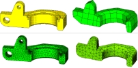
The images below show a CAD model which has been imported, defeatured to varying levels, and meshed using CADfix.
 Meshing Meshing
CADfix meshing provides mesh generation functionality to create volume, surface and beam element meshes. These can be quad or triangular meshes for surfaces, tetrahedral or hexahedral for volumes. The finite difference mesher produces Cartesian grids for wires, surfaces, and volumes.
Meshing tools enable the setting up of controls for meshing, whether element size, meshing algorithm, or the lattice grading for finite difference meshes. A range of mesh quality checking facilities is provided to ensure mesh integrity.
 Interfaces Interfaces
A range of import and export translators are provided for leading analysis packages, including:
- ABAQUS
- Nastran
- PAFEC
- Dyna3D
An advanced data access toolkit is available for users to create interfaces to their own analysis codes, and a neutral mesh format is also provided.
|


 Software Solutions-Inter Operability-


